Arduino Uno Pwm Code | Arduino Tutorial
Di: Jacob
In this tutorial, you’ll learn how to do Arduino L298N Motor Driver Interfacing and use the L298N with Arduino to control the speed and direction of DC motors. 0 – 10) and may result in a value of 0 not fully turning off the output on .
Secrets of Arduino PWM
Si yo quisiera, mediante una señal PWM -es decir conectando el arduino a un canal de una emisora rc- controlar que el motor gire en un sentido, hasta un final de carrera físico -mediante un microswitch- y después una vez parado, volver a ponerlo en funcionamiento, pero en sentido contrario, hasta llegar a otro final de carrera -otro microswitch-. On an Arduino Uno, PWM output is possible on digital I/O pins 3, 5, 6, 9, 10, and 11.
Arduino PWM analogWrite() Tutorial
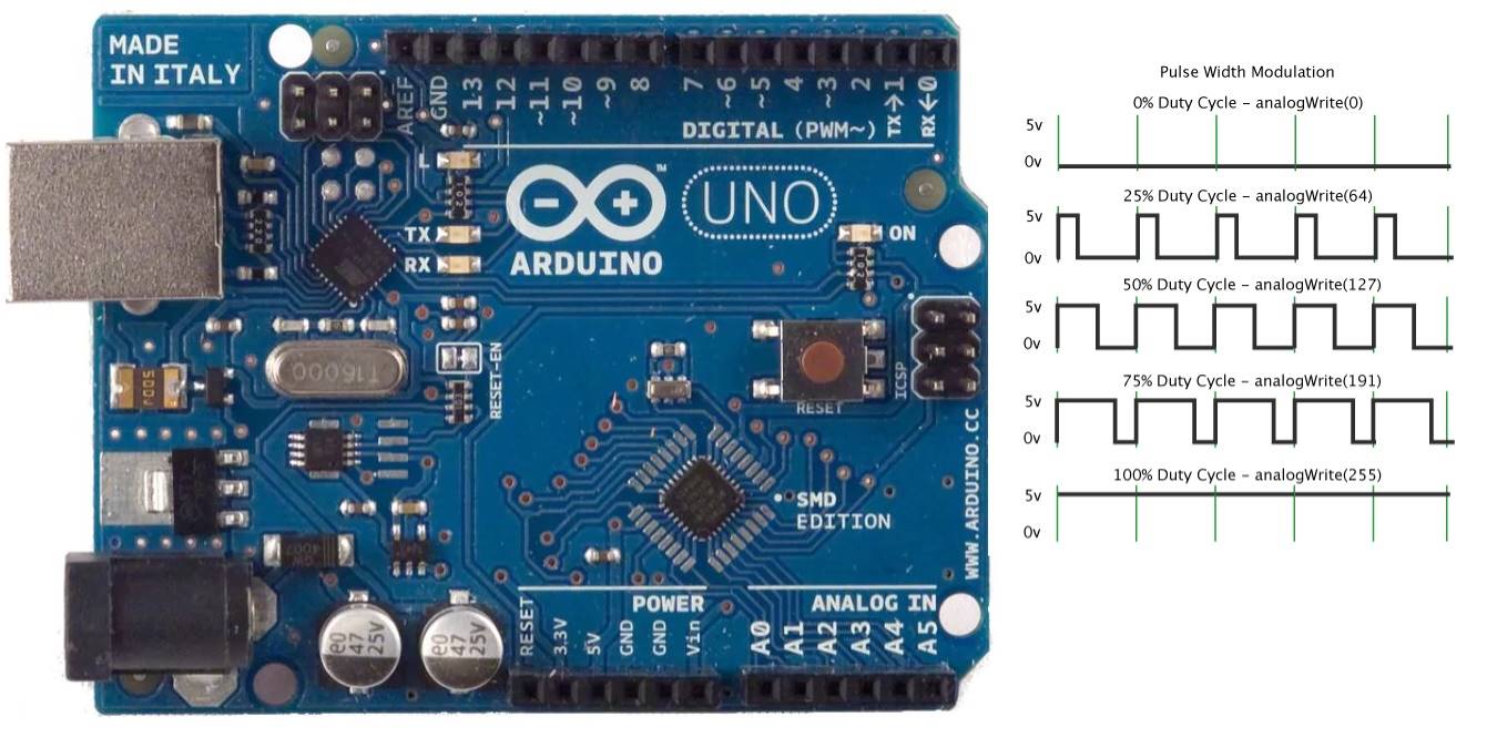
What is Arduino PWM? Pulse width modulation or pulse duration modulation is a technique where we vary the width of a square pulse to control the power supplied to any . In the setup() function, we don’t need to declare pin 10 as output because later on in the loop() function we will call the analogWrite() function . Code Explanation.infoEmpfohlen auf der Grundlage der beliebten • Feedback
Use PWM output with Arduino
Using PWM pins in Arduino Uno is explained in the C code given below. On these PWM pins, the duty cycle of the PWM pulse, which is nearly 500 Hz, is controlled by the analogWrite . The Arduino’s programming language makes PWM easy to use; simply call analogWrite (pin, dutyCycle), where dutyCycle is a .The code below shows two pwm signals.Pulse Width Modulation is a technique by which the width of a pulse is varied, keeping the frequency constant. These PWM-enabled pins are illustrated in the image below.
Frequency changing of pwm pins of arduino uno
This project contains generic but efficient code that can be used to simply read an RC receiver (or any other .But the servo just sits still when i upload my sketch to my Arduino Uno.

Axial Fan, 12 VDC. This example uses the built-in LED that most Arduino boards have.hartmut-waller. Pulse Width Modulation, or PWM, is a technique for getting analog results with digital . Add PWM output to your sketch using the .
Richtiger Anschluss Motor an PWM
In diesem Arduino-Tutorial wird gezeigt, wie man eine LED mit der PWM-Technik dimmt.Use PWM output with Arduino.In this tutorial, I will explain the theory Pulse Width Modulation (PWM), and how to use it with an Arduino to control the brightness of an LED. Manchmal ist die .PWM bedeutet Pulse Width Modulation und beschreibt ein Verfahren, bei dem der Strom in schneller Abfolge ein- und abgeschaltet wird.
Set PWM frequency to 25 kHz
R1 is a current . It contains everything needed to support the microcontroller; simply connect it to a .Beliebige PWM Frequenz erzeugen – Deutsch – Arduino Forumforum. Arduino supports an 8-bit wide pulse that can . Read PWM, Decode RC Receiver Input, and Apply Fail-Safe. I still cant get it.It depends upon what type of Arduino you have, but on many Arduinos the resolution of micros() is something greater than 1 microsecond. 220 ohm resistor. In fact, micros() can NEVER provide information about fractions of a microsecond. But after you set a PWM value of 0, the Arduino analogWrite function has shut off PWM, so you will have to make a call to ‚arduino_FastPWM()‘ again to restart PWM. Using PWM in your sketch.In Arduino we can use the analogWrite (pin, value) method to create a PWM signal on the digital pins. This will be noticed mostly on low duty-cycle settings (e. Here is the code:
How to Control Servo Motors with Arduino (3 Examples)
Ich habe nun schon mehrere Anleitungen angesehen, aber sie sind unterschiedlich. Pin5 gives the original signal and Pin6 gives the inverted signal, which means that the signals are behaving in anti-parallel manor. Bei Verwendung der Funktion analogWrite variiert die PWM-Frequenz von 0 bis 255 und entspricht einem Impulsfüllfaktor von 0 bis 100%.h void setup() { uint32_t pwm_duty = 32767; uint32_t pwm_freq1 = 300000; uint32_t pwm_freq2 = 300000; // Set PWM Resolution pwm_set_resolution(16); // Setup PWM Once (Up to two unique frequencies . Hardware Required.Pulse Width Modulation, or PWM, is a technique for getting analog results with digital means. And we’ll create a couple of Arduino DC Motor Control With L298N . The Arduino Uno is equipped with 6 channels capable of 8-bit PWM. This feature can be used to build a plethora of fun audio projects, but also work as professional lab equipment as a cheap function generator, for example. PWM Pins on Arduino Uno.It also involves reconfiguring the three timers, which means loosing the Arduino . SG90 Micro-servo motor.20 Hz (The default) 2) For D5 & D6: 976.
Arduino Mega, Nidec UltraFlo Fan, 4 Wires
Pins marked with the symbol ‘~’ indicate their PWM support.It provides Arduino IDE to write code & connect the hardware devices like Arduino boards & sensors. #include pwm01.The PWM outputs generated on pins 5 and 6 will have higher-than-expected duty cycles. Please suggest me how to create a suitable PWM signal for controlling a servo. Thus, with a frequency f c = 500Hz, the period is ˝ c = 1=f c ˘2ms. Apps and platforms.In this tutorial, you’ll learn how to use Arduino PWM analog output pins using the analogWrite () function.Simple Pulse Width Modulation with analogWrite.Now, let’s delve into PWM in Arduino.We will take a look at three different pins: brake, pwm & direction, where we will create a simple sketch that uses all three of them.It is available in the File->Sketchbook->Examples->Analog menu of the Arduino software.55 Hz thank you . We will learn to generate fixed frequency, variable frequency, fixed duty cycle, and variable duty cycle PWM signal . We are going to increment and decrement this number by button press. The LED is connected at digital pin 12 of the arduino.Easy to use code to measure PWM signals (<2. In the circuit, the slider of the 50K potentiometer is connected to analog input pin A0 of the arduino.
Arduino Tutorial
Easy to use code to measure PWM signals (<2. Der Arduino ist eine tolle Erfindung, die es .This example shows the simplest thing you can do with an Arduino to see physical output: it blinks the on-board LED. Value is the turn ON duty cycle, between 0 (always off) and 255 (always on). Nov 13, 2019 • 115610 views • 27 respects. Anyway, in this little post, I’m going to show you how to play 16-bit PWM on Arduino through a simple but an adept trick. des ATmega 328P ein. This project showcases the versatility of PWM in controlling motor speed.Controlling the Brightness of an LED using the PWM on Arduino UNO.Hello friends, I hope you all are doing great.25 kHz 4 Pin PWM Fan Control with Arduino Uno. Arduino Board; optional. Arduino Forum Frequency changing of pwm pins of arduino .
Arduino PWM output and its uses
So at PIN3 we are getting PWM output. Arduino Uno has 8-bit PWM channels. We will design a small code in which we will be controlling a dc motor’s speed using the Arduino PWM Pins but before going into the details, let me first give you an . I tried to play with the prescaller but I could not get the . Learn how to use PWM (Pulse Width Modulation) output with Arduino. Afterwards we show different application example of PWM which includes . When you turn the potentiometer, the motor’s speed will change smoothly, thanks to PWM control.5Khz) plus a dedicated function to calibrate the input from an RC receiver, including fail-safe.The Arduino UNO R4 WiFi has a built in DAC (Digital-to-analog Converter) which is used to transform a digital signal to an analog one. On these pins the analogWrite function is used to set the duty cycle of a PWM pulse train that operates at approximately 500Hz2.
PWM pins in Arduino: Arduino Uno R3 has 6 PWM pins that are 3, 5, 6, 9, 10, and 11.ccPulsweitenmodulation – Programmieren mit Arduino – . Jul 27, 2019 • . Ein Zeitintervall ist dabei 20 Millisekunden .20 Hz (The default) These frequencies are optimum for . Here is the code const int pwmPin = 9; // PWM control pin .
How to Use Pulse Width Modulation on the Arduino
comEmpfohlen auf der Grundlage der beliebten • Feedback
Basics of PWM (Pulse Width Modulation)
The PWM frequency equals to 7.
Arduino & Advanced 16-bit PWM
These PWM pins are represented by the symbol ‘~’.Write a code using the Arduino PWM library to adjust the motor’s speed based on the potentiometer’s position. Arduino Uno has 6 on-board PWM channels which can be used to . This is because of interactions with the millis() and delay() functions, which share the same internal timer used to generate those PWM outputs. Just for testing, I think this code has to be worked out further for use in a real application. In this tutorial, we will learn how to control a DC motor, using the Motor Shield Rev3, a shield compatible with the Arduino UNO.Code Arduino für Steuerung der PWM-Frequenz. You are going to have difficulty measuring 6. This is my vode.It’s the next tutorial in our new Arduino Tutorial for Beginners series.In this tutorial, we will learn to generate PWM using Arduino. That symbol tells us that these pins have PWM support.But I think you then can use ‚analogWrite‘ with PWM values 0f 1.In diesem Beitrag über Timer und Pulsweitenmodulation (PWM) tauche ich in die Tiefen des Arduino UNO bzw.

comPWM With Arduino – Step by Step Guide – Instructablesinstructables. I have no idea how to alter the PWM signal from 500HZ (default) to 50HZ, so instead i decided to do it with the help of digitalWrite() and delay() functions.In addition we will also take a look at how we can power our project, using an external . We’ll start from the basics of PWM signal, its frequency, duty .Arduino UNO is a microcontroller board based on the ATmega328P. Components and supplies. Auf dem Bild wird mit . These pins can generate a pulse as per the given inputs.
Timer und PWM
Here the brightness of an LED can be controlled using a potentiometer. Use pin 5 or 6 for about 1kHz (post#3). USB-A to Mini-USB Cable. These pins are marked with the negation sign “ ~ “. Digital control is used to create a square wave, a signal switched between on . The Arduino PWM pins are 3,5,6,9,10 and 11. it produces 3 PWM signals with variable Duty Cycle and Variable Frequency. It’s a fundamental concept in robotics and automation, allowing .Is the experiment finished? Of course not.On an Arduino Uno, PWM output is possible on digital I/O pins 3, 5, 6, 9, 10 and 11.In this article we will learn how pulse width modulation works and how to generate pulse width modulation signals with the Arduino. What is Pulse Width Modulation (PWM)? . As with conventional digital I/O, the pinMode function must be called rst to . This LED is connected to a digital pin and its number may vary from board type to board type. The value parameter is used to change the duty cycle but the PWM . Die Pulsweitenmodulation auf den Arduino Uno und Nano arbeitet an den digitalen Pins – 3, 5, 6, 9, 10 und 11 mit 488,28 . Hardware and Software Requirements. How can I increase it up to 10 Khz and keep both signals behaving in the same way.

In diesem Beispiel wird der digitalen Pin 3 als PWM-Ausgang verwendet.Was bedeutet PWM? Wie stelle ich Duty-Cycle und Frequenz eines PWM-Signals ein? Was sind PWM-Signale? PWM steht für Pulse-Width-Modulation oder auf deutsch: .Here ‘pin’ represent the pin number where we need PWM output we are putting it as ‘3’.8 microseconds. The circuit diagram is shown below. In this article, you will learn: About the DAC feature .This one could be the simplest example of PWM control using arduino. It has 14 digital input/output pins (of which 6 can be used as PWM outputs), 6 analog inputs, a 16 MHz .Here is the default frequency of each PWM pin of Arduino UNO: 1) PWM frequency for D3 & D11: 490. Sie können aber .gatsby-image-wrapper [data-placeholder-image]{opacity:0!important}