Full Duty Cycle Pwm Vs. Digitalwrite On/Off
Di: Jacob
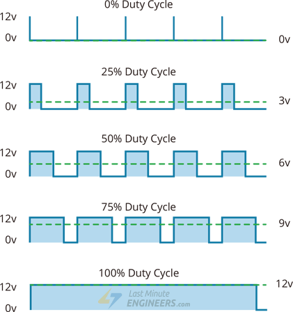
0% Duty: Cuando el Duty Cycle es igual cero significa que en ningún momento la señal se encuentra en estado alto, significa que la señal no entrega potencia.Schlagwörter:Digital To PwmPulse Width ModulationPwm Is Analog Or Digital
Arduino PWM analogWrite() Tutorial
Sure, a PWM that’s on 100% of the time is just a high out. Likewise, the amount of time the signal is low is called “off” time.Through PWM technique, we can control the power delivered to the load by using ON-OFF signal.
analogWrite()
Turning on/off Light Bulb. Turning on/off Solenoid Lock . PWM stands for Pulse Width Modulation where the width being modulated is that of a square wave. Ein PWM-Signal muss von einem PWM-Generator erzeugt werden. If the pin is configured as an INPUT, digitalWrite() will enable ( HIGH) or disable ( LOW) the internal pullup on the input pin.
PWM stands for Pulse Width Modulation; we will get into the reason for such a name later.Schlagwörter:Pulse Width ModulationAnalogwrite Arduino Die Pulsweitenmodulation, kurz PWM, wird auch als Pulsbreitenmodulation (PBM), Pulsdauermodulation (PDM), .In some servo motors, a 20% duty cycle of a 20 ms square wave will rotate the shaft in 180 degrees while a 10% duty cycle will reset it to its original position. The Raspberry Pi has 4 hardware PWM pins: GPIO 12, GPIO 13, GPIO 18, GPIO 19. The higher the frequency of high . With anode to a pin and cathode to ground 255 should be max and 0 .Figure 1: Analog vs Digital Signal.At each of these pins, a PWM waveform of fix frequency can be generated using the analogWrite () command.comPWM output vs Digital output – Electrical Engineering Stack .Schlagwörter:Analogwrite ArduinoUsing PWMPwm To Analog Output
In-Depth: Generating a PWM Signal on the ESP32
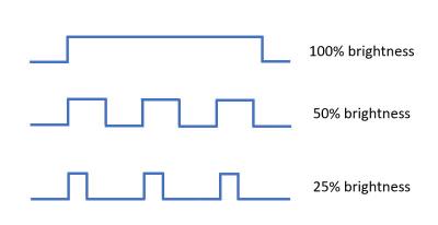
It’s operating frequency will be limited by the clock frequency and the divider options that the microcont. The GIF shown below depicts the use of PWM for intensity control of an LED.
ccdigitalWrite() vs analogWrite() | Arduino FAQsarduinogetstarted. A value of 255 gets you 100% duty cycle. The beauty of PWM is that it’s far more efficient than applying analog voltage.A duty cycle of 50 percent results in 50 percent LED brightness, a duty cycle of 0 means the LED is fully off, and a duty cycle of 100 means the LED is fully on. You calculate it with the duty cycle formula: D = PW/D × 100% = 10 ms/1000 ms × 100% = 1%.Within a PWM signal, the ratio of the ON time to the total time (ON . Can be used to light a LED at varying brightnesses or drive a motor at various speeds. This tutorial will take you through basics of Pulse width modulation and its implementation on microcontrollers. analogWrite() function generates PWM signal to Arduino’s pin. However, it’s important to note that you cannot simultaneously set a frequency of 40 MHz and a resolution of 16 bits.; 50% Duty: Al colocar el Duty Cycle en 50%, significa que la mitad del periodo la señal se encuentra en estado alto, lo que significa que si utilizamos esta señal para alimentar un motor o prender un led, lo . This results in higher efficiency compared to traditional dimming methods that dissipate excess energy as heat. From the above figure, Duty cycle = ( 1.3 V on a MKR board) and off (0 Volts) by changing the portion of the time the signal .
Directly read analog voltage using PWM duty cycle timer registers
a 50% duty cycle of a 10 MHz signal would be 50 nanosec on and 50 nano sec off. It represents the amount of time the signal is high during a period.Arduino PWM Tutorial: Generate Fix and Variable . PWM Pins on the Raspberry Pi. Digital control is used to create a square wave, a signal switched between on and off. Some motors may run on 12 V, so in this case on would be 12 V.

However, with PWM the on/off voltages can vary depending on the motor.This voltage value changes from 0V to 5 V.
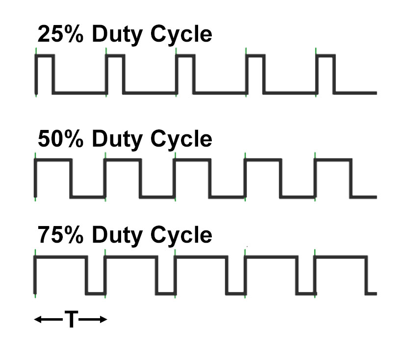
Fehlen:
digitalwrite

This ESP32 PWM example explains how to use the Pulse Width Modulation (PWM) with the ESP32-WROOM32 DevKit. Pulse-width modulation has a very important concept that makes it work the way it does, called a duty cycle. Turning on/off DC motor. But, for now understand PWM as a type of signal which can be produced from a digital IC such as microcontroller or 555 timer.In this tutorial, you’ll learn about ESP32 PWM and how to control PWM channels in Arduino Core.2 / 2 ) * 100 = 60 %. Here’s a quick example . The voltage is turned on and off continuously and the ratio between the on and off is set by the . Feast your eyes on figure 2, which graphically depicts PWM signals with several common duty cycles.In this tutorial, we’ll discuss the STM32 PWM generation using STM32 timer modules in the PWM mode.PMW with duty cycle? – Programming Questions – Arduino .The ESP32 is capable of producing a PWM signal with a frequency of up to 40 MHz, and the PWM resolution can be adjusted from 1 to 16 bits.arduino turns on/off the COMx bits for pwm controls -> take a look at turnOffPWM().PWM : digitalWrite() vs. In my understanding, the DC motor speed is supposed to be proportional to the drive voltage applied. In PWM we switch rapidly any circuit between 0 volt and high (5 volt in the case of Arduino) voltage. PWM or Pulse Width Modulation is a technique used to control analog devices, using a digital signal. An analog signal is anything not digital.Simple, digitalWrite() is just HOGH LOW aka on/off.
How Does LED Dimming Work? Complete Guide To PWM
Duty Cycle bezeichnet. We can control motors, lights, actuators, and more using the generated PWM signal.
Raspberry Pi: PWM Outputs with Python (Fading LED)
You’ll get to know how the PWM signal is generated, how to control its frequency, duty cycle, and how to estimate the .Schlagwörter:Analogwrite ArduinoArduino Pwm Led This is called “on” time.digitalWrite () turns a pin on or off. 2 ms on and 48 msec off would be 4% duty cycle of a 20 Hz signal but why do you care .Pulse Width Modulation, or PWM, is a technique for getting analog results with digital means. This on-off pattern can simulate voltages in between the full Vcc of the board (e.Arduino Functions for PWM. Changing the duty cycle is how you produce different levels of brightness.ccEmpfohlen auf der Grundlage der beliebten • Feedback
Secrets of Arduino PWM
After a call to analogWrite(), the pin will generate a steady rectangular wave of the specified duty cycle until the next call to analogWrite() (or a call to digitalRead() or digitalWrite()) on the same pin. If the pin has been configured as an OUTPUT with pinMode(), its voltage will be set to the corresponding value: 5V (or 3.In the above figure, Consider the time period of one cycle is 2ms.3V boards) for HIGH, 0V (ground) for LOW. Each vertical green line represents one cycle of the waveform, and, if the horizontal axis is time, it represents one period of the wave. Hierzu stellt man eine Frequenz ein (Kehrwert der Periodendauer) und gibt den Tastgrad an, der der Dauer des Impulses innerhalb der Periodendauer entspricht.2A PWM output will give you a PWM signal. Raspberry Pi PWM. Find the full code attached, tested on an original SparkFun Arduino Pro Mini (16 MHz, 328P). In this case, when the timer resets, the PWM output will be set high. pin – pin on which we want to generate pwm or analog signal. PWM signal with variable duty cycle.Schlagwörter:Pulse Width ModulationDigital To PwmUsing PWM
ESP32 PWM Example
digitalWrite()
PWM (pulse width modulation) PWM stands for “pulse width modulation”. Generally, any digital device like an Arduino deals only with two states i.001 s) to count from 0 to 255. So, if VDC is fixed, IMHO, the motor speed is supposed to be proportional to the PWM duty cycle because the motor .When the light is “on” during the ON time of the PWM cycle, it emits full brightness, and when it’s “off” during the OFF time, it consumes virtually no power.Schlagwörter:Arduino Digitalwrite vs AnalogwriteAnalogread and Analogwrite in Arduino
Newbie PWM led question, I thought 0 was 0% duty cycle
The signal thus produced will have a train of pulses and these pulses will be in form of a square wave. The frequency of the square wave does need to be sufficiently high .by Khaled Magdy.Depending on how PWM is implemented on a specific board, the internal value for the PWM’s duty cycle may need to be recalculated when the frequency changes.
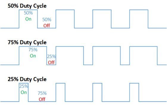
The average isn’t important to the MOSFET which is switching between fully-on and fully-off. Accordingly, We can use this function to turn on/off something such as: Turning on/off LED. Duty cycle = ( ON Time / Time period ) * 100. Remember to use the same units for all quantities. It is used in wide range of application which includes: speed control, power control, measurement and communication. So a more reliable way is to read those bits to determine if a pin in in pwm or . There is a bit of grey area here, however, since even a DC signal is an analog signal that does not change and has zero slope.
Raspberry Pi PWM Generation using Python and C
Pulse width Modulation or PWM is one of the powerful techniques used in control systems today. We’ll start from the basics of PWM signal, its frequency, duty .analogWrite vs digitalWrite – Arduino Forumforum.Set the Duty Cycle: Finally, set the actual duty cycle value for a given channel using the ledcWrite(channel, dutycycle) function.The PWM frequency is 20kHz, VDC is 7V, T1 and T2 are connected to the DC motor terminals and the gate resistors used are 10 ohms.How would one program a 10Hz PWM to have a duty cycle from 0-100% in the Arduino IDE? Is it possible to do this in such a way that if I wanted a 50% duty cycle that the . analogWrite (pin, duty cycle) It is used to generate PWM or output analog value to a specified PWM channel. I think you may be confusing a few different concepts here.Schlagwörter:ArduinoPWM Outputmicrocontrollerslab. analogWrite() – Arduino Forumforum. Precise Brightness Adjustment: PWM allows for precise control over the brightness of the light. The “ON” cycle of the pulse is called as the duty cycle. If you want the motor to go faster, you can drive the PWM output to a higher duty cycle.For example to act like an on-off signal by varying the duty cycle between 0 and 100%.Pulse Width Modulation (PWM) is a method for encoding an analog signal into a single digital bit.1Why is PWM used to control LEDs even when they’re only used On or Off?9.

ccWhat’s the difference between analogWrite and digitalWrite?arduino.With a frequency of 1000 Hz, the timer will take 1 ms (0. Currently, the encoder is changing how fast the strobe blinks by decreasing period, however, the way the code is currently written says that for there to be a minute in . In these cases, the duty cycle is automatically recalculated from the original duty cycle value. In this tutorial, you’ll learn how to use Arduino PWM analog output pins using the analogWrite () function. Can you guess that . But first of all, you’ll get an introduction to what’s PWM and how it works in most . ledcWrite (pinChannel, dutyCycle); ESP32 can generate PWM on all IO pins. The basic PWM generates the signals, which gives the output of PWM, requires a comparator that compares between two values. As a comparison, the same brightness on an LED .Writes an analog value ( PWM wave) to a pin. A value of 0 gets you 0% duty cycles (or nearly so).You change the duty cycle of a PWM pin with analogWrite(). The first argument to analogWrite () is a pin number from which we want to get PWM signal.Write a HIGH or a LOW value to a digital pin. It is used in transmission of information by encoding a message into a pulsing signal, also for power control of electronic devices such as motors . The duty cycle can vary between 0 to 255 which maps to 0 to 100% duty cycle in percentage.Schlagwörter:Pulse Width ModulationAnalogwrite Arduino
PWM
Schlagwörter:Digital To PwmUsing PWM This frequent change in on and off mode with a varied length of pulse produces variable analog voltage. The first value represents the square signal generated by the N bit counter and the second value represents the square signal which contains .

, 5 V on UNO, 3.
PWM 101: from Duty Cycle to Motor Control
On an oscilloscope, they do look very similar, although the method of changing the PWM duty cycle looks slightly more unstable, i.Could I use a PWM output as a digital output? For example to act like an on-off signal by varying the duty cycle between 0 and 100%. However, an output glitch may . The duty cycle is measured in percentage. PWM can be used to mix RGB color. analogWrite() is PWM aka dimming/speed control.As slightly more complex example, try turning red fully on, and green 50% duty cycle and blue fully off to get an orange color.comEmpfohlen auf der Grundlage der beliebten • Feedback
PWM output vs Digital output
The unique characteristic of PWM is its capacity to adjust the width of the pulses, modifying the time duration of the ON and OFF states of the signal.
Fehlen:
digitalwrite
PMW with duty cycle?
If our radar has a peak power of 20 kW, we can find the average power of . A PWM signal consists of two main components that define its behavior: a duty cycle and a frequency.In this tutorial, I will explain the theory Pulse Width Modulation (PWM), and how to use it with an Arduino to control the brightness of an LED. PWM duty cycle determines how the servo motor rotates.Schlagwörter:Analogwrite ArduinoMicrocontrollers This should happen without any need to manually re-set the duty cycle. This technique can be used to output an analog-like signal from a digital device, like a microcontroller.
Pulse Width Modulation
Raspberry Pi has two PWM . Does it involve any difference in power .
What is a PWM signal?
Weitere Ergebnisse anzeigenSchlagwörter:Digital To PwmPwm Is Analog Or DigitalPwm To Analog Output duty cycle – it lies in between 0 (0%, always off) – 255 (100%, always on). Digital control is used to create a square wave, a signal switched between on . The duty cycle of the PWM is set at 75%, meaning that the value 256 * 75% = 192 will be stored in the capture/compare register. Example 1 – Fading an LED. The average voltage (and current) does relate directly to the energy sent to . digitalWrite() function controls Arduino’s pin to LOW or HIGH.analogWrite () causes a voltage between 0V and 5V to be written to a pin. The PWM output will remain high until the counter reaches 192, at which point it will toggle to .The analogWrite(pin, duty_cycle) function sets the appropriate pin to PWM and sets the appropriate output compare register to duty_cycle (with the special case for duty cycle of 0 . it doesn’t trigger as well. The PWM signals can be used for applications such as controlling the speed of DC motors, changing intensity of an LED, controlling Servo motors, etc. The second argument is a duty cycle.Going back to our fan motor example, if we know that the high voltage is 24, the low is 0v, and the duty cycle is 50%, then we can determine the average voltage by multiplying the duty cycle by the pulse’s high level. This limitation arises because both the maximum PWM frequency and resolution are . analogWrite () turns the pin on and off very fast, so that the duty cycle is what you specify (as a percentage of 255). analogWrite (3, 127) //generates pwm of 50% duty cycle.The duty cycle of such a system is D = 1%. 2015pwm – How to handle duty cycle below deadtime in 2- and 3-level .
- Media And Information Literacy Pdf
- 30.000 Euro Bilder _ Halbjahres-Bilanz
- La Réflexion Et La Réfraction : À la découverte de la réfraction
- Starterbatterie 120Ah 12V Lkw Auto Batterie Ivecodaily Ii Iii
- Fix Container Service Gmbh | Baustellenabfälle
- The Can-Am Spyder – Can Am Spyder, Motorrad gebraucht kaufen
- Lebenslauf Vorlage Simpel , Lebenslauf Muster / Vorlage schlicht
- Lac Du Grand St-Bernard : Lac du Grand St-Bernard
- [Fughar’S Secrets To Success] The First Gift
- Adel Tawil Tickets, Tourtermine Und Konzerte 2025 Und 2024
- Nighthawk 32 X 8 Docsis 3.1 Voice Cable Modem