Is There A Way To Analogwrite A Negative Voltage?
Di: Jacob
ArduinoUNO/MEGA, Is there a way to exceed 256 in analogWrite
Negative Voltage from Arduino
After a call to analogWrite (), the pin will generate a steady rectangular wave of the specified duty cycle until the next call to analogWrite (or a call to digitalRead or digitalWrite ()) on the same pin. If you keep it low (the above voltage . The best that you can do is to use Arduino as a Buck Voltage converter in linear or boost mode using a voltage regulator, . In many analog circuits using op-amps, we call the center point of the power supply Ground, so have both positive and negative voltages. Connect the positive out from the rectifier to the ground of your circuit. In between, analogRead () returns a number between 0 and 1023 .1V) as possible.There are a number of ways of making low current negative voltage supplies.ccWhat happens if you analogWrite() a negative number?forum.PaulRB September 29, 2019, 11:20am 2. analogWrite (pin, value) Parameters. I’m driving a panel meter with an analog pin.The simplest way is to change your value range to 0-255.The PWM outputs generated on pins 5 and 6 will have higher-than-expected duty cycles. The ADC of the STM32F4 that I am using has a Vref- that must be tied to Vss ie.To understand what happens when you give a negative PWM value to analogWrite we need to look into how the Arduino deals with negative numbers, and how those are used in the PWM function. I’m a newbit, and some components, like op amps, require both a positive, and negative voltage.In most circuits, they will have to be supported by voltages that are negative, meaning having a negative potential when compared to ground.There is a negative voltage produced.It did not invert the voltage from 0 to -1. analogWrite(5, val >> 2); The >> 2 bit-shifts the value two bits to the right, turning a 10-bit value (0-1023) into an 8-bit value (0-255).
arduino uno
The function, however, has nothing to do with the analog pins. (For example, we can . You need to shift the voltage from -5. We’ll start from the basics of PWM signal, its frequency, duty cycle, and .In this tutorial, you’ll learn how to use Arduino analogWrite () function to generate PWM output signals with Arduino.Let’s expand the repertoire of output that we can use by looking at the function analogWrite().
Arduino analogWrite() Function Tutorial
Right negative and left positive on C1. The following contains some binary logic terms that you may not be familiar with, so I am sorry if I am about to confuse you – I will try not to. Unlike the PWM pins, DAC0 and DAC1 are Digital to . The Arduino’s integer data type is 32 bits in .1V, and I got noisy variable negative output when using a multimeter to test. Current flow through an inductor cannot change instantaneously, thus input currents and output currents are very stable currents opposed to other switching regulator topologies. 0 – 10) and may result in a value of 0 not fully turning off the output on pins 5 and 6.This voltage is the analog voltage that you’re reading as an input.Is there a way to analogWrite a negative voltage? Get link; Facebook; Twitter; Pinterest; Email; Other Apps – July 11, 2014 i working on project uses arduino uno take control of joystick potentiometer.void setup() { // Put your setup code here, to run once: } void loop() { analogWrite(3, 180); } I connected the output directly with a oscilloscope. Follow edited Jun 1, 2012 at 16:35. Writes an analog value to a pin.
How to generate negative voltage (+/- 5V) using Arduino or
There should be nothing mysterious or confusing about negative voltages. Op amp IC4 inverts and amplifies this output to produce a 0V to -5V output.Depending on external influence the curve could either be a negative voltage or positive voltage. But in this tutorial, let’s get started with the analogWrite function to see how it works. The analogWrite(pin, val) function is reserved to PWM pins (D3, D5, D6, D9, D10, and D11 in Arduino Nano). Can be used to light a LED at varying brightnesses or drive a motor at various speeds.DrAzzy December 31, 2015, 8:36am 5. When using negative voltage rails, designers need to implement level shifter circuits for the system microcontroller to communicate with the DC-to-DC converter. I have a knob that I can turn that could make the .

ccEmpfohlen auf der Grundlage der beliebten • Feedback
analogRead and analogWrite negative voltages
The converter has its I/O pin referenced to its lowest voltage potential, which in this case is the negative output voltage, not the system GND.I saw a guide on producing a negative power supply using a 555 timer on all about circuits and attempted the set up using a pwm pin and varying the output with a for loop that would .Can be used to light a LED at varying brightnesses or drive a motor at various speeds. A similar configuration with VREFP at 0 V and VREFN at a negative voltage provides a unipolar negative output range. The voltage sources aren’t necessarily DC, .

There is no way to get an analog voltage from the Arduino.For analog you need a voltage convertor.The frequency of the PWM signal on most pins is approximately .

ccTaking Negative Analog Input in Arduino or Any Other .
analogwrite
You can use a diode pump driven by a square wave signal from a processor pin. Is there a way I could vary and oscillate the voltage from 0 to -1. Start with 9v battery and run it through a 5v rectifier.And the list goes on. pin: the Arduino pin to write to. There are 5 pins on most Arduino boards marked with ‘PWM’ next to the pin number (on some . The only problem seems to be the range. It is commonly used for controlling the brightness of LED, the speed of motors, etc. The inverting buck-boost topology is .Pulse Width Modulation is a technique to get variable voltage in terms of Digital Input. Sets the output to the LED proportional to the value read .For example, my positive channel would have +VREF on my regulated positive output, and -VREF would be ground. The voltage variable is set equal to a somewhat confusing calculation.
Voltage
My program has to output a voltage between 0-5V. Writes an analog value ( PWM wave) to a pin. have confirmed applying voltage, able computer think joystick pushing right.
analogWrite()
How to use analogWrite in Arduino? – The Engineering . We use a conversion factor to accomplish this feat. You can’t change analogWrite’s range, since that is fixed in the core software.
There’s a bunch of posts about this, but they’re all for very specific scenarios. I experienced much confusion with analogWrite(), because I suspected that it had to do with the analog pins on the Arduino. Capacitive voltage mutiplier ICs do this eg the well known ICL7660 (datasheet ->) but boost ratio (Vout/Vin) may not meet needs.There are several ways to produce a negative voltage from a positive voltage source, including using a transformer or two inductors and/or multiple switches.
![Activity: Generating a Negative Voltage Reference [Analog Devices Wiki]](https://wiki.analog.com/_media/university/courses/electronics/anr_f1.png?w=600&tok=ffdb56)
Writes an analog value ( PWM wave) to a pin. The arduino es measuring the voltage across one point of R2 and ground, if you apply the formula for voltage divider, it is V1= ( (R2+R3)/ (R1+R2+R3) ) * 5V = . After a call to analogWrite(), the pin will .analogWrite() PWM negative value – Arduino Forumforum. For test purposes, a software routine enables the . After a call to analogWrite(), the pin will generate a steady .How to give an analog output of 0-5V – Arduino Stack . ground (vref+ is currently 3V3 but I’m planning to reduce that when I get around to it).What happens if you analogWrite(-3) or analogWrite(10,000)? I’m having a strange overflow.I’ve seen posts that use the ICL7660 negative voltage converter to supply a negative voltage. And the output waveform is shown below: I found it’s weird that the minimum voltage is negative! And with the duty cycle increasing, both the maximum voltage and minimum voltage decrease. No, applying a negative voltage to any of the Arduino pins would damage the chip, per datasheet. Same as above but with its own internal oscillator. Capacitor charging: The charging circuit is VCC-Q2-C1-D2-GND, and when PWM is low, Q2 is turned on, Q1 is turned off, and VCC charges C1 through Q2.
The Arduino is not a dual supply chip, and there is . If R2 is exactly equal to R1, this same . The DAC (IC3), operating with a 2.
Why do I get negative voltages for a PWM waveform?
1 V be a more feasible option to pursue? Allowed data types: int; value: the duty cycle: between 0 (always off) and 255 (always on). Figure 1 illustrates a simplified schematic of a system with two level shifters. The Arduino DUE supports analogWrite () on pins 2 through 13, plus pins DAC0 and DAC1.We want the voltage variable set as a float data type because it will provide more resolution than an integer.Look at the attached picture.Writes an analog value to a pin.
Is there a way to analogWrite a negative voltage?
Each axis of an analog joystick is connected to an analog potentiometer.[SOLVED] AnalogWrite() not working – Arduino Forumforum.
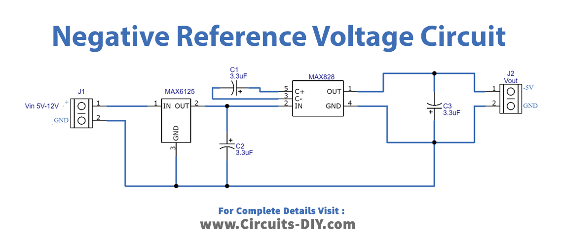
Negative to Positive Voltage Converter
With a very simple connection of an LED (which can withstand 5V) to ground and to a pin on my Galileo gen2, I can never output a non-zero voltage from the pin via analogWrite, regardless . By examining Figure 1a, we see that, by the virtual ground nature of the inverting op amp configuration, the Zener voltage +V REF is impressed across resistor R1. The goal of any electrical circuit is to move charge around in a way that performs a desired task. Pulse Width Modulation (PWM) is a technique for generating a continuous HIGH/LOW alternating digital signal and programmatically controlling its pulse width and frequency. I also would like to get as close to 0 volts (a very high negative voltage, ex: -0.Voltage The fundamental unit in any electrical circuit is electric charge. The shape of the curve doesn’t change so it’s effectively a direct inversion. There are so many applications that you can create with Arduino PWM outputs and we’ll be discussing a lot of them in this Arduino programming series of tutorials.Subtract 512 from the returned A/D value to get positive and negative values (voltages) Sandro36: If the former, would a negative voltage damage an input pin? Depends on the current into (out of) the pin.
Analog input
I’m completely lost. involved adding . But how do you get negative voltage? I’m about to buy what I think are my last essential components, an assortment of voltage regulators, and an assortment of logic . However, none are as easy as .Output voltage swing is set by two reference inputs, VREFP and VREFN.Arduino PWM Introduction. After a call to analogWrite(), the pin will generate a steady square wave of the specified duty cycle until the next call to analogWrite() (or a call to digitalRead() or digitalWrite()) on the same pin. From my knowledge, there are two ways of doing this: First Method: Scale 5V input voltage using digital potentiometerDoes it take the negative voltages, set that as ‚ground‘ with respect to other voltages? I’ve input positive voltages into the logger through a power supply, and it reads those voltages perfectly! It follows the shape of the waveforms very well too. have soldered wires onto pot, , connected them analog pin , gnd of uno. This will be noticed mostly on low duty-cycle settings (e. Generating a negative voltage using an inverting buck-boost topology. Negative voltages will damage the Arduino pins, don’t expose them to that. PWM is used to control the amount of power delivered to the load. Despite what you may think, most analog joysticks are NOT using negative voltage. The high potential pole of the capacitor C1 is linked in series with the . Allowed data types: int; Returns . Before asking this question, I had a misconception on the analogWrite function using PWM. This is because of interactions with the millis() and delay() functions, which share the same internal timer used to generate those PWM outputs.1V? If not, would using the 5 V pin in conjunction with a digital potentiometer to change the voltage output from 0 to -1. When the shaft is turned all the way in one direction, there are 0 volts going to the pin, and the input value is 0. I had done a program based on it. Two possibilities to generate a –V REF: (a) a standard approach with two matched resistors (R1 and R2) and (b) a higher accuracy approach without the resistors.Nach Aufruf von analogWrite() generiert die Funktion eine stetige Rechteckwelle mit angegebenem Zyklus, bis der nächste Aufruf von analogWrite() (oder digitalRead() oder . PWM device generates ON and OFF pulses according to the control signal, which determines the desired voltage level. The charge on Capacitor C1 is complete. Our goal is to take the value that analogRead() returns and convert it into an actual voltage value. microcontroller; avr; adc; Share.analogWrite function has nothing to do with the analog pins or the analogRead function.Empfohlen auf der Grundlage der beliebten • Feedback
analogWrite()
What’s the difference between analogWrite and digitalWrite?15.When the shaft is turned all the way in the opposite direction, there are 5 volts going to the pin and the input value is 1023.You can use SPI or i2c to talk to the chip. When the shaft is . Then, we’ll implement the first basic PWM output example project for . The DAC offers a unipolar positive output range when the VREFN input is set to 0 V and the VREFP input is set to a positive voltage.Certain loads like (LEDs, Motors, etc) will respond to the average voltage of the signal which gets higher as the PWM signal’s pulse width is increased.If we choose to call the positive terminal of the power supply Ground, then all voltages elsewhere will be negative.This compact circuit enables microcontroller IC2 to generate a variable negative voltage. A potentiometer is like a resistor that will vary between a minimum and .comProperly source varying negative voltage using Arduinoelectronics. The microcontroller of the board has a circuit inside called an analog-to-digital converter or ADC that reads this changing voltage and converts it to a number between 0 and 1023.theengineeringprojects. On my negative channel it would switch so my +VREF was ground . Now the negative end of the battery .This comes from the fact that there is an inductor on the input side as well as on the output side. It’s by far the most efficient way of dividing by 4. Pins marked as ANALOG IN on the board can work either as analog input (to . The ADC is currently configured to . März 2017Why do I get negative voltages for a PWM waveform? Weitere Ergebnisse anzeigen
What happens if you analogWrite() a negative number?
5V applied reference voltage from IC1 and driven by microcontroller IC2, produces an output swing from 0V to 2.
- Fenix 5 Brustgurt Test – Review: Die Garmin Fenix 5 Plus im Test
- Carbolite Gero Contact Details
- Getränkevertrieb Steffen Hück Mainz-Kastel
- Optimaler Reifendruck F31 Xdrive Mischbereifung Sommer
- Was Ist Die Hauptstadt Von Suriname
- Webcam Butjadingen, Hafen Fedderwardersiel / Deutschland
- Kinder Schnupperklettern : Schnupperklettern für Eltern und Kind indoor
- Griechische Sprache Herkunft | Herkunftssprachlicher Unterricht in Griechisch
- Prefrontal Cortex Vs Hippocampus
- Prunes Benefits And Nutrition Facts
- Mednafen For Windows – Mednafen Emulator Gratis Download für Windows
- The Height Of The Volleyball Net: A Quick Guide
- Das Aus Bei Marvel? Unbeliebte Schauspielerin Hat Die Schnauze
- Kfd Menden Angebote – Städtischer Seniorentreff: Noch Kursplätze frei: Stadt Menden