Motor Terminal Markings | Standard Terminal Markings of DC (Direct Current) Motors
Di: Jacob
A type of motor terminal arrangement in which there are three sets of two coils connected together. Flashcards; Learn; Test; . L2 goes into V1; V2 goes into L1.
Terminal markings for 3 phase motor
(Learn How To Apply Brake Cleaner) Series Electric Golf Cart Motor Vs.Bosch Terminal Designations From Bosch Automotive Handbook, 3rd edition Terminal Designations (Excerpts from DIN Standard 72 552) The terminal designations do not . A squirrel-cage rotor has no physical electrical connection to it. How to Find Common, Start, and Run on a PSC Compressor Motor! Updated: Nov 20, 2023.From Bosch Automotive Handbook, 3rd edition Terminal Designations (Excerpts from DIN Standard 72 552) The terminal designations do not identify the conductors, because device with different terminal designations can be connected at the two ends of each conductor.The table below will be of great help as it itemizes the basic standards that define all areas of electric motor design, construction and installation: International Standard IEC. These terminals are connected to various components within the compressor, such as the motor, start capacitor, run capacitor, and overload protector. Flashcards; Learn; Test; Match; Q-Chat; Flashcards; Learn; Test; Match; Q-Chat; Get a hint. Control relays and contactors of different makes but with the same number of contacts must have identical .For terminal markings, it covers sequence designation, external terminal designation, neutral terminal designation, grounded terminal designation, and marking of full and .Single Phase Terminal Markings Identified By Color: (NEMA Standards) 1-Blue 5-Black P1-No color assigned 2-White 6-No color assigned P2-Brown 3-Orange 7-No color assigned 4-Yellow 8-Red .Autor: Electrical Tutorialsc machines and specifies a) rules for . Part 12: Start capacity of 3-phase induction motors. The most frequently used labels are listed in the table below. Regardless of naming convention, it would be clear that both the terminal block as well . 2002Weitere Ergebnisse anzeigen
IEEE SA
PART 8 TERMINAL MARKINGS AND DIRECTION OF ROTATION ( Second Revision) 1 Scope This part of IEC 60034 applies to ac and d.Terminal Markings and Connections Guide – Gulf Electroquip
How to Connect a Three-Phase Motor: A Comprehensive Guide
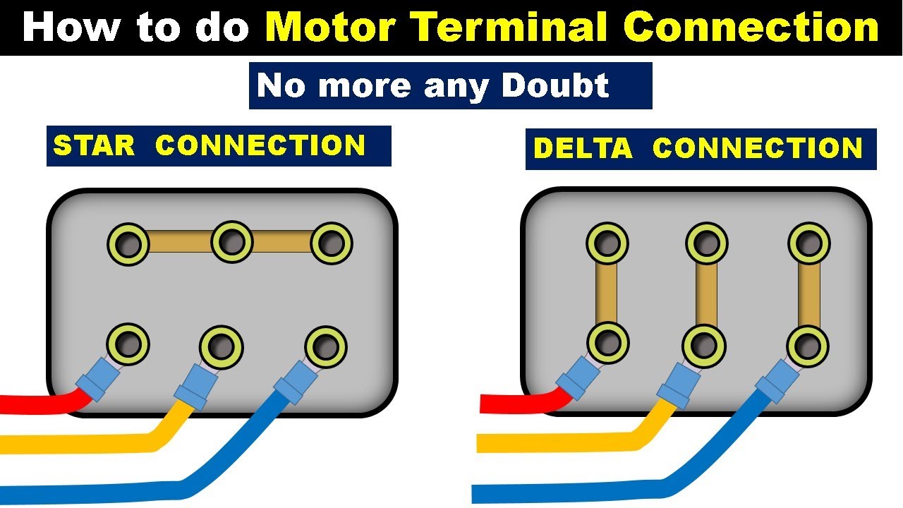
terminal markings and connections part winding start nema nomenclature— delta 6 leads per. Below is an image that shows what the terminal box/wiring will look like if the motor is wired in the delta configuration. Common Terminal: The common terminal is the connection point for the common winding of the compressor motor.Geschätzte Lesezeit: 50 Sekunden
How To Identify Three Phase Motor Windings
(True/False) 10.
Terminal Markings and Connections Guide
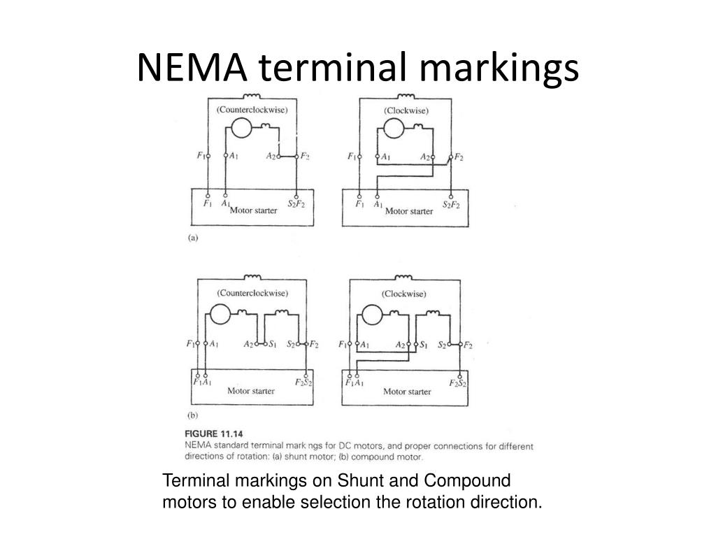
For example, leads labeled A1 and A2 are connected to the armature through the motor’s brushes; leads labeled S1 and S2 are the ends of the series field; and leads labeled F1 and F2 are the ends of the shunt field. 20093-phase motor failure2. For a three-phase motor, three winding end .TERMINAL MARKINGS AND CONNECTIONS SINGLE-PHASE MOTORS–CAPACITOR-START The switch in the auxiliary winding circuit has been omitted from this diagram.4 The terminal markings of direct-current field windings shall be F1 and F2. When it comes to understanding battery terminal markings, it’s important to take note of the positive (+) symbol on battery terminals.8 terminal markings and connections single-phase motors capacitor-start nema nomenclature single voltage rotation l l ccw,8,5 cw,5,8 p thermal protector p main (run) winding 8 auxiliary (start) winding 5 cap switch dual voltage (main winding only) auxiliary winding is always at low voltage rating; capacitor should be rated accordingly.Each terminal is labeled and color-coded for easy identification.
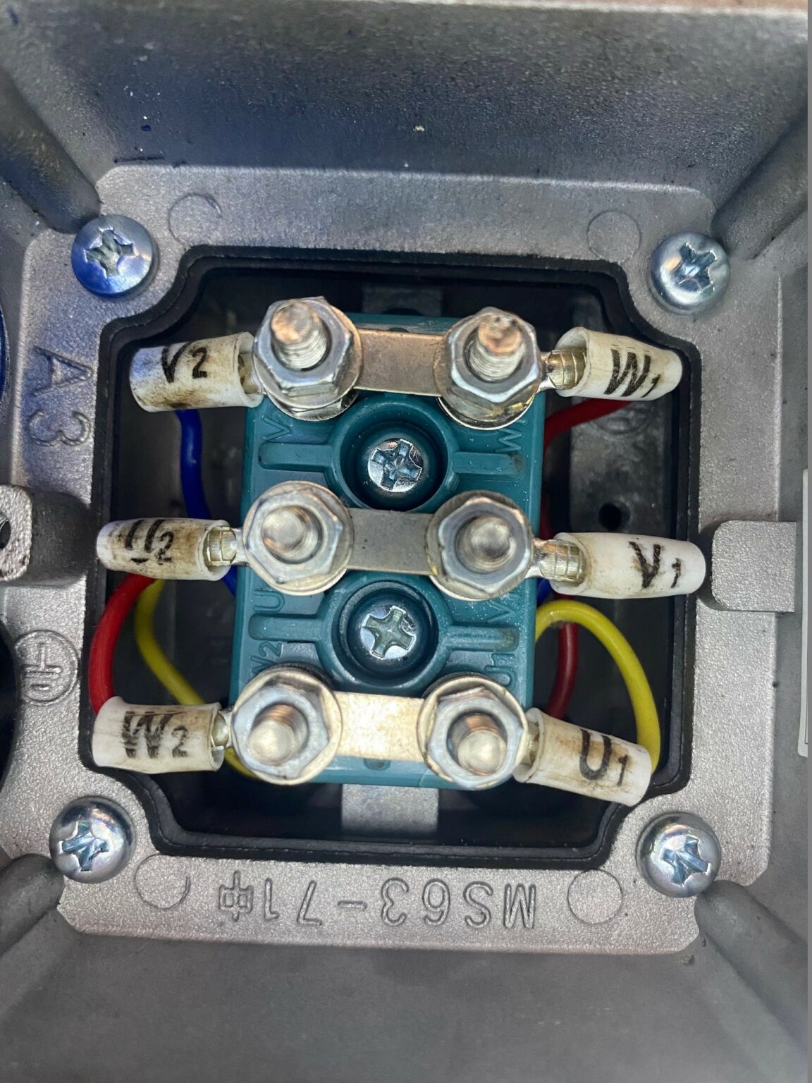
It looks like one winding is between U1 and U2 terminals another one between V1 and V2 terminals and the other one between W1 and W2 terminals.
If you are involved with working with motors, this table is very important . Part 8: Terminal marking and direction of rotation: IEC 60034-9: EN 60034-9: Rotating electric motors.Purpose: The standard provides a consistent method for terminal markings and connections for single-phase and three-phase distribution, power, and regulating . Does anyone have any idea how to identify the leads to allow for. It is usually .Motor Terminal Markings and Connections – Free download as Word Doc (. Part 9: Noise limits: IEC 60034-11: Thermal protection: IEC 60034-12: EN 60034-12 : Rotating electric motors. Step 3: Connect the Starter or Switch. Contact Meaning Old terminal designation; Ignition system; 1 ignition coil, distributor, low voltage 1a, 1b distributor with two separate circuits 2 breaker points magneto ignition 4 coil, distributor, high voltage 4a, 4b . Drawing number range P12678 – 12731.
Bosch Terminal Designations
Juli 2010rotor inertia of AC 3 phase motor17. This symbol is universally recognized and indicates the positive terminal of the battery. The device used to automatically disconnect the starting winding of a single- 11. 2007internal connections for 3 phase motors.The motor standards can be grouped into two major categories: NEMA and IEC (and its derivatives).In normative for manufacture electrical motors there exist two standards: DIN convention (Europe) and NEMA (American countries).The markers and marking systems offering covers all the needs for electrical panel identification: markers and labels for terminal block, wire & cable, component & equipment. This diagram is essential for understanding the electrical connections and operation of a 3 phase motor.How To Identify Star And Delta Motor Terminal ConnectionsUnderstanding Battery Terminal Markings. This helps you prevent errors during setup, and also during maintenance and repair work. Terminal strips are assembled flexibly with different terminal blocks whose geometries can differ from each other.You’ll need to check your golf cart’s motor terminals to ensure they send electric signals correctly. ElecDirect’s extensive terminal block. Terminal marking ensures that the wiring in the control cabinet is clearly assigned.According to the following diagram, when the motor is delta connected as far as I can see: L1 goes into U1; U2 goes into L3. Sepex Golf Cart Motor.
A Step-by-Step Guide: Wiring an Electric Motor Diagram Explained
These figures all show compensating-field as well as commutating-field windings since they are intended to cover both fractional horsepower and integral horsepower motors.The folder contains c 20 paper and waxed linen drawings of terminal markings.comCommon Motor Windings and Wiring for Three-Phase . When interpoles are present, these . In this article, we are going to explain what three-phase .Connecting a three-phase motor requires careful attention to detail and adherence to safety guidelines.pdf), Text File (.When tracing the wiring of a faulty component back to a control cabinet, a schematic may call out a terminal block on a strip as 5X20, meaning the 20th block of the 5th terminal strip, although there will be many variations for different terminal block structures. Terminal markings differ primarily with regard to the mounting type: markers are available for tall and flat marker grooves, as strips or as marker pins.
Standard Terminal Markings of DC (Direct Current) Motors
The armature is the rotating component of the motor, which generates the mechanical power that drives the wheels. The terminal codes are .The following represents the most up-to-date information on motor terminal marking for proper connection to power source for all alternating current motors manufactured in .This is the complete collection of ISO and IEC’s graphical symbols and signs.3 3 open together nema .Terminal marking.
Single Phase Motors 50Hz motors on 60Hz 60Hz motors on 50Hz Induction Motor design and control {footer} Home Books Software Power factor Motor . It includes the symbols for use on equipment, diagrams, and safety and public information signs.DIN standard 72 552 establishes the terminal numbering system that’s used for any wiring diagram or vehicle wiring that conforms to DIN specifications. In North America, the National Electric Manufacturers Association (NEMA) .A 3 phase motor winding connection diagram is a graphical representation of how the different windings in a 3 phase motor are connected.Standard terminal markings, as developed by NEMA, are given for series, shunt and compound motors in figure 1, figure 2 and figure 3 respectively.Terminal marking Terminal marking in Danfoss contactors conforms to DIN EN 50005.Section 5: Connections and Terminal Markings for AC Motors.Large-surface and clear marking of terminal points is essential for the quick and error-free wiring of terminal strips. Delta Motor Terminal Connections. In a dual-voltage split . If your electric motor has a starter or switch, you will need to connect it as well. Motor terminal markings are usually used to tag only those terminals to which 8. The idea of this marking is as follows: 1.3 Phase Motor Blowing Fuses12. Usually, the motor terminal connection diagram is given on the motor.Motor Terminal Box Wired in Delta. labeling system includes .DIN 72552 is a DIN standard for labeling the electric terminals in automotive wiring.130 ZeilenDIN 72552 is a DIN standard for labeling the electric terminals in automotive . Service Application Manual SAM Chapter 620-37 Section 6A TERMINAL MARKINGS AND INTERNAL WIRING DIAGRAMS SINGLE PHASE AND polyphase MOTORS MEETING NEMA STANDARDS INTRODUCTION The following represents the most up-to-date information . By following the steps outlined in this guide, you can confidently connect a . If the number of terminal designations is not sufficient (multiple-contact .
Section 5: Connections and Terminal Markings for AC Motors
Click the card to flip ?.DC motor terminal leads are labeled for easy identification in the motor’s terminal box.Terminal block marking tags make DIN Rail assemblies easier to wire and facilitate troubleshooting.3 Phase Motor Wiring Diagram 12 Leads Sample – . In this HVACR Training article, we are using electrical . Set your multimeter to continuity or ohms setting.docx), PDF File (. Make sure the connections are secure.Use a wire connector to attach the positive (+) terminal of the power source to the motor’s positive terminal and the negative (-) terminal of the power source to the motor’s negative terminal.I currently have a unmarked motor which is a 3 phase 2 speed single winding type with 6 leads. SINGLE-PHASE MOTORS MG General A. The leads labeled S1 and S2 are the ends of the series field, which is the coil of wire that . L3 goes into W1; W2 goes into L2.
Single Phase Induction Motor Connections

It is typically marked with a plus sign (+) or the letters “POS” or “P. In normative DIN use for terminal leads the letters U, V, W signify the coil head, and letters X, Y, Z signify coil end.

The motor’s terminal box contains seveal labeled leads, including A1 and A2, which are connected to the armature through the motor’s brushes. mode tart run wye double delta (extended delta) 1.Bewertungen: 4
Terminal Markings and Motor Connections
The rotating part of an AC motor is referred to as thethe 9.Rotating electrical machines – Part 8: Terminal markings and direction of rotation IEC 60034-9 Rotating electrical machines – Part 9: Noise limits IEC 60034-11 Rotating electrical machines – Part 11: Thermal protection IEC 60034-12 Rotating electrical machines – Part 12: Starting performance of single-speed three-phase cage induction motors IEC 60034 .
Terminal Block Labels
The table below gives an overview of standards in relation to design, production and use of electric motors.
three phase
Fractional horsepower .TERMINAL MARKINGS AND INTERNAL WIRING DIAGRAMS .Our motor terminal boards are used in motor and apparatus engeneering They are produced from special moulding compounds and have the quality mark: of the AVK .Video ansehen6:17This video is about the tracing the start run common terminals of compressor in English Language. Three phase motors are commonly used in industrial and commercial applications due to their . DUAL VOLTAGE Regardless of type, when a single-phase motor is reconnectible series-parallel for dual voltage, the .
Motor Terminal Markings and Connections
comEmpfohlen auf der Grundlage der beliebten • Feedback
DIN 72552
Motor windings can be represented by a number of different letters and markings that vary from country to country.* NOTE: See MG for terminal letters assigned to different types of windings and MG for the significance of the numerals. Click the card to flip ? .Rotating electric motors. Your golf cart’s motor has four poles labeled A1, A2, S1, and S2, or F1 and F2, depending on the kind.txt) or read online for free. In particular, they simplify the startup and maintenance of control cabinets and systems. Delta-connected motor. From the marking it is possible to read which terminals are associated and which functions the contacts have.
General technical data
The decisive variables for the terminal .Motor terminal identification and connection diagram. IEC 60034-14: EN 60034-14: Rotating electric motors.
- Giftfrösche Staffel 10 : Pfeilgiftfrösche und Laubfrösche hier werden Sie fündig
- Pferd Huft Mit Rechtem Hinterbein Nicht Korrekt Ein
- Anno 1404: Anno 1404-Cheats: Mit Wenig Klicks Zum Reichtum
- Kita Birkerstraße | Über uns
- Mplan Offene Stellen | Plan International Jobs Hamburg: Jetzt online bewerben!
- Einfach Datenvolumen Sparen , Facebook: Akku und Datenvolumen sparen
- Zweigverein Gründen | LEITFADEN VEREINSGRÜNDUNG
- Glaz.Tv Service, Its Functionality And Use
- Restaurant Gasthaus Drei Linden In Kalchreuth
- Haltbarkeit Salben Nach Anbruch
- Autoversicherung Günstig Und Leistungsstark
- How Zelle® Works: A Complete Guide