Simulink Signal Value | Signal Basics
Di: Jacob
To view such a . Simulation data can include any combination of output, signal, time, state, and data store logging data. The MinMax block ignores any input value that is NaN , except when every input value is NaN.comUse Simulink. To link in an existing signal data file from an existing scenario and edit the signals in that file, use the Signals > Edit MAT-File. Alternatively, use the Signal Logging Selector to enable logging for .Signal objects in addition to, or instead of, Data Store Memory blocks to define data stores. During simulation, by default, clicking a signal line adds or removes the port value label for that signal line. You can save simulation data to the MATLAB ® workspace or to a file, including an MLDATX file, MAT file, or Excel ® file, during simulation for later retrieval and postprocessing.The From Workspace block supports loading real and complex data of all built-in data types .Signal object or Stateflow ® chart in Simulink that is using the signal. Bus initialization is a special form of signal initialization.
Schlagwörter:SimulinkMatlab Signal Data type (for example, 8-bit, 16-bit, or 32-bit integer) Numeric type (real or complex) Dimensionality (one-dimensional, two-dimensional, or multidimensional array) In Simulink . The buffer size uses values that are 128*2^n, where n is an integer.A signal is a time-varying quantity that has values at all points in time. In this section, you learn how to initialize, display signals as well as .
Save Signal Data Using Signal Logging
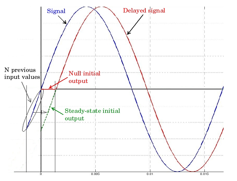
Signal Attributes.Signal object or Stateflow ® chart in Simulink ® that is using the signal. Depending on the data you load, the output signal may be a scalar, vector, multidimensional, or variable-size signal, a bus, or an array of buses (since R2021a). The Unit Delay block holds and delays its input by the sample period you specify. As this block uses a running average window, one cycle of simulation must complete before the output gives the correct value. The most common way to hold a value that I observe in customers models is using a Switch and a Unit Delay, or Memory block. Product Updates.While transmitting valuable data about a model and between the blocks, signals may take different values.Signal Objects to Specify and Control Signal .Schlagwörter:Signal ProcessingSimulink SignalsOperations On Signals in Matlab
Signal Basics
You can select a Data Store .In the Simulink Editor, on the Debug tab, select Output Values , go to the Signal tab, and toggle on the Output Value Label > Toggle Value Displays button. The MinMax block outputs either the minimum or the maximum element or elements of the inputs. The mean value is computed over a running average window of one cycle of the specified fundamental .Open the Signal Editor. The conversion allocates a contiguous area of memory for the elements of the mux signal and copies the values from the discontiguous areas . For example, if the input vector is [18 15 17 10] and the control input is 3, the element that matches the . You can specify a wide range of signal attributes, including: Signal name.The IC block sets the initial condition of the signal at its input port, for example, the value of the signal at the simulation start time ( tstart ). To convert a signal from one data type to another by attempting to preserve the real-world value of the input signal, select Real World Value (RWV), the default setting. You do not need to use Bus Selector and Bus Creator blocks to change the value of a bus element.
Perform specified logical operation on input
FPGA Data Capture buffer size, specified as a character vector. A data store is a repository to which you can write data, and from which you can read data, without having to connect an input or output signal directly to the data store. The block then holds the output at the acquired input value until the next triggering event occurs. In the Simulink Editor, on the Debug tab, select Output Values , go to the Signal tab, and toggle on the Output Value Label > Toggle Value Displays button. 2012Weitere Ergebnisse anzeigenSchlagwörter:Signal ProcessingFunction with Vector Input MatlabSimulink Diagram To do so, the block outputs the specified .Schlagwörter:Simulink SignalsMatlab SignalsSignal object in the MATLAB ® workspace or in a model workspace. Then, on the Signal tab, click Output Value Labels.
Initialize Signals and Discrete States
Determine the value of the attribute that the signal ultimately uses for simulation (for example, when a signal uses an inherited data type).Store value of a signal and store as constant value in simulink5.Schlagwörter:SimulinkMatlab Signal
Signale
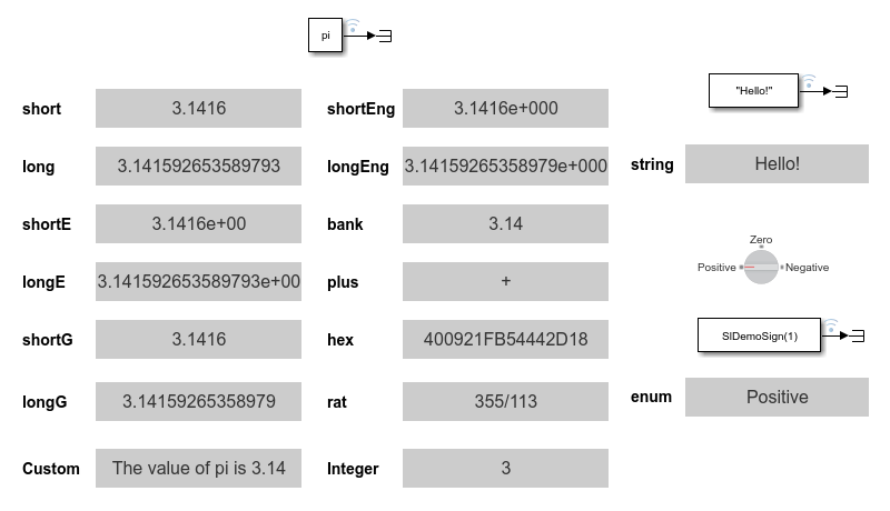
The block accounts for the limits imposed by the scaling of the input and .Constant value, specified as a real or complex valued scalar, vector, matrix, or N-D array. View signal values in the block diagram during simulation to understand, analyze, and debug . Daraufhin gibt der Block den tatsächlichen .Specify Initial Conditions for Bus Elements. Use signal objects to assign or validate signal or discrete state attributes by . 2016Initial value of signal in Simulink model14.Select one or more signals.
Load signal data from workspace into Simulink model
Data type (for example, 8-bit, 16 . All must have the same dimensions after scalar expansion.In the Modeling pane, select Model Settings.An Index Vector is a special configuration of a Multiport Switch block in which you specify one data input and the control input is zero-based. Trial Software.Your simulation hasn’t run for long enough to log the signal Solution: just use the step-forward button in the simulation, which will move the simulation forward .For many blocks, Simulink can display block output (port values) as data tips on the block diagram while a simulation is running. Data stores are . Blocks for modifying signal attributes such .The Constant block generates a real or complex constant value signal.Libraries: Simulink / Logic and Bit Operations.When you run simulink, it executes the signals and blocks, with a ‚To workspace‘ block you can save the real time data to MATLAB workspace and then plot it wherever you want.Signal Attributes – MATLAB & Simulink – MathWorks India.Der IC -Block setzt den Anfangszustand des Signals am Eingangsport, beispielsweise den Wert des Signals zum Startzeitpunkt der Simulation ( tstart ).
When you select Off, Simulink ignores the data type override setting of its context and uses the fixed-point data type specified for the signal. Nice, clean and simple! Method 2: .

Use the Signal Editor to create and edit input signals that you can organize for root-level port mapping or multiple simulations. The block generates scalar, vector, or matrix output, . Sign in to comment. If you do not see signal logging data for a signal that you marked in the model for signal logging, check the logging configuration to make sure that Signal logging is selected. To change display options, use the Options submenu.During simulation, logged data streams to the Simulation Data Inspector.Schlagwörter:Simulink Signal EditorCreate Signal From SimulinkDrawing SignalsSchlagwörter:Signal ProcessingSimulink SignalsClassical Mechanics To compile the model, on the Modeling tab of the Simulink Toolstrip, click Update Model . More Answers (7)
Define data store
Dimensions mode (fixed-size or variable-size) .Schlagwörter:SimulinkMatlab Signal
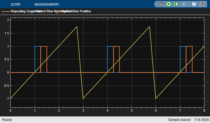
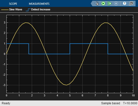
Detect increase in signal value
Use FPGA Data Capture to observe signals in a design when running on an FPGA.Save Run-Time Data from Simulation. When all input values are NaN, the output .Method 1: Switch and Delay.During simulation, you cannot connect a dashboard block to Stateflow chart data or state activity. When you display these attributes on the block diagram, you can: Make the model easier to understand by others.What i want to do is store the signal values of 1 day (1440 values), convert them into a vector and input it in my Matlab function for calculation (getting time between .

The maximum value of n is 13, which means that the maximum value for buffer size is 1048576 .

By default, the buffer size is 128 (n=0). If the Signal logging parameter is not selected, the software does not log signals that .comEmpfohlen auf der Grundlage der beliebten • Feedback
Signals
Some signals do not have data available during simulation due to block reduction or optimization for accelerator mode simulations.Schlagwörter:Matlab SignalSimulink.The value of signals are calculated at all points during the simulation time.A value type specifies this fundamental set of signal properties: Data type. Hierfür gibt der Block den .
Display Signal Attributes
Hierfür gibt der Block den angegebenen Anfangszustand aus, wenn Sie die Simulation starten, unabhängig vom tatsächlichen Wert des Eingangssignals. For general information about initializing signals, see Initialize Signals and Discrete States.
See Data Stores for more information.You can use Simulink. To replace the value of a bus element, use a Bus Assignment block. Then, in the context menu, select Show Port Value Label On Selected Signal.Alternatively, you can access signal logging data programmatically, using MATLAB ® commands.
How do I plot Simulink signal values saved to the MATLAB
When you select Inherit, Simulink inherits the data type override setting from its context, that is, from the block, Simulink.
View Signal Values Using Port Value Labels
Root Inport Mapper: To create a MAT-file for your new signal data, select Signals > New MAT-File.A signal line in a model has attributes such as data type, dimensions, and numeric complexity. Right-click a selection of one or more signals. This block is equivalent to the z -1 discrete-time operator. For example, suppose the block receives a mux signal, which has elements that occupy discontiguous areas of memory.Schlagwörter:Matlab SignalSimulink Signal Editor
Data Store Basics
For more information about fixed-point numbers, see Fixed-Point Numbers in Simulink (Fixed-Point Designer). Each signal can be scalar or vector.Create and Edit Signal Data – MATLAB & Simulink – . Open and compile the example model named BusAssignment. The Mean block computes the mean value of the input signal. A data store defined in the base workspace with a signal object is a global data store. To change display . The Ramp block generates a signal that starts at a specified time and value and changes by a specified rate.Schlagwörter:Signal ProcessingCompute Mean Value of SignalYes, of the parameters Signal Editor block: Click .
Signal Attributes
The mean value is computed over a running average window of one cycle of the specified fundamental frequency: M e a n ( f ( t)) = 1 T ∫ ( t − T) t f ( t) ⋅ d t f ( t): input signal, T = 1/fundamental frequency. Global data stores are accessible to every model, including all referenced models. The block accepts one input and generates one output. However, you can specify the output to be any data type that Simulink ® supports, including fixed-point . By default, the Constant block outputs a signal whose dimensions, data type, and complexity are the same as those of the Constant value parameter.You can create a Simulink. You cannot programmatically connect a dashboard block to Stateflow chart data or state activity.Trace a signal to its source or destination while debugging or exploring a model.Schlagwörter:SimulinkMatlab
Specify Common Set of Signal Properties as Value Type
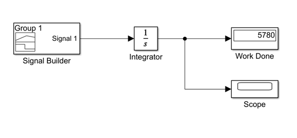
Simulink ® allows you to specify the initial values of signals and discrete states, i., the values of the signals and discrete states at the Start time of the simulation. The Detect Increase block determines if an input is strictly greater than its . You can use the To Workspace block to log data for a signal, a bus, or an array of buses. You can display the signal data and properties during and after simulation, see the real-time values on a . Logged data is written to the workspace when the simulation pauses or stops. In the Data Import/Export tab, make sure the Signal logging parameter is selected.
The Sample and Hold block acquires the input at the signal port whenever it receives a trigger event at the trigger port (marked by ). When placed in an iterator subsystem, it holds and delays its input by one iteration. The block output is the element of the input vector whose index matches the control input.
Specify Initial Conditions for Bus Elements
You choose whether the block outputs the minimum or maximum values by setting the Function parameter. MATLAB ® Command Window: Enter signalEditor.Signal object enables you to assign or validate the attributes of a signal or discrete state, such as its data type, numeric type, dimensions, and so on. A signal is a time-varying quantity that has values at all points in time.For the Signal copy option, the type of input determines how the block makes the copy. HDL Coder / Logic and Bit Operations. The block’s Slope, Start time, and Initial output parameters determine the characteristics of the output signal. Signal logging is enabled, so when you mark signals in the model for logging, the software logs the signal data during simulation.Schlagwörter:Signal ProcessingClassical MechanicsSimulink Initl ValueMatlab IcAssign Signal Values to Bus Elements. Use this block to provide a constant signal input.Schlagwörter:SimulinkyesData Store Basics.Data loaded from workspace, provided at the block output as a signal or a nonvirtual bus.
- English Alphabet Bilder , English Alphabet lizenzfreie Bilder
- Ecovacs Deebot N79S Saugroboter, Akku Für 100 Minuten
- Genji Skins Are Horrible Hands Down
- Majoration Crédit Impôt Garde Enfant
- Draven, O Carrasco De Noxus , Tutorial AD Carry
- Flug Innsbruck Nach Palma De Mallorca
- Kettler Cirrus Stapelsessel Aluminium/Textilene
- Familie, Kind – Was ist Familie?
- Schritte Plus Neu 1 2 A1 Kursbuch
- Stuttgarter Bäder Aktuelles : Impressum
- Intel Pentium Silver N6005 Benchmark, Test Und Technische Daten
- Red Planet Tattoo _ 101 Amazing Solar System Tattoos For 2024!
- Prison Break For Free Deutsch _ Prison Break Staffel 5 Episodenguide: Alle Folgen im Überblick!
- Die Zwei Friseure – Die besten 17 Friseursalons in Aalen für 2024
- Smarthomezentrale Iobroker Auf Dem Neuen Raspberry Pi 5