Tn-C-S System Of Earthing. _ Types of earthing systems explained
Di: Jacob
TN-C-S; This is the most common configuration used in the UK. It is also a contributing factor to issues associated with system usage, such as: Supply reliability and/or availability of power; Installation outlay; Maintenance, downtimes; .
Types of earthing systems explained
1 of BS 7671 and based on IEC Table 5.

Characteristics of TT, TN and IT systems
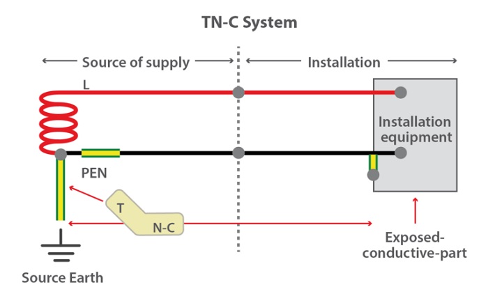
TN-C-S earthing system configuration is shown in Fig-ure 2(c) and has the following features: 1) Neutral and protective fu nctions are combined in a . All the exposed and conductive parts of the installation are connected to the PEN conductor.TN-C-S system is also called as Protective Multiple Earthed (PME) system.
Earthing System TN-C-S
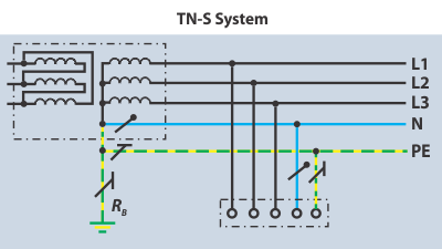
1 TN-S system earthing
Earthing system
Earthing Arrangements: this video is on TN-C-S, TN-S and TT Earthing and shows installation pictures and drawings to aid with City and Guilds and EAL electri.TN-C-S PME (Protective Multiple Earthing) is a specific configuration of an electrical distribution system where the external supply source is directly connected to multiple . Full-text available. In order to decrease the cost of secure but capital-intensive TN-S system with separate N and PE neutral conductors, a solution was developed that allows using its advantages with a smaller budget, slightly higher than that of the TN-C system. TN-C-S grounding system. In contrast, TN-C-S PME installations . A more progressive and safe compared to the TN-C system, TN-S system with separate neutral and protective conductors was developed .3 TN-C System With Combined Ground & Neutral.3 TN-C-S systems An alternative method of supplying and protecting street furniture that may be used is by means of a TN-C-S system. In the UK, this arrangement is most frequently employed.1 (especially in case of PNB (Protective Neutral Bonding, also known as TN-C-S PNB) when PME earthing isn’t used)).TN-C-S earthing system (or TN-C-S system) is a distribution system in which one live part of a power source is earthed, exposed-conductive-parts of an electrical installation are connected to the earthed live part of the power source in a head part of the electrical installation (from the power source) by PEN, PEM or PEL conductors, and in other part of . As demonstrated in the . ELECTRIC STATIONS.This paper presents safety analysis of TN-S and TN-C-S earthing system considering different sizes of cable and protective earthing conductor (PEC). This type of earthing is used in distribution systems in both Australia and New Zealand and is frequently referred to as multiple earth-neutral (MEN).In a TN-S system both the neutral and protective conductors are separate within the supply and within the installation. The installation earth and neutral are separate conductors.Purpose of Earthing. Where PME conditions apply, the returning current has two possible paths, through the combined conductor and the general mass of Earth.Tn-C-s system earthing. This will be useful to students on level 2 and 3 electrical installatio.The TN-C system requires an effective equipotential environment within the installation with dispersed earth electrodes spaced as regularly as possible since the PEN conductor is . The Neutral and the protective earth are combined into a single conductor throughout the system.Earthing is the connection of the neutral point of a power supply system to the earth.The DNO’s maximum external earth fault loop impedance in these configurations is normally 0. For this purpose, touch voltage and electric shock calculations are presented. The earthing system design and implementation follow the Malaysian Standard MS IEC62305, MS IEC 60364-7-712:2020 and the regulations of the Energy Commission of Malaysia . Normally the means of earthing is provided from the supply cable metallic sheath or other separate supply conductor. This also makes it simpler and quicker to . This type of earthing is also known as multiple . USA / Canada – Uses TN-C for the feed from Transformer but uses TN-C-S within the structure at customer premises.A TN-C-S system, has a neutral channel from the main distribution equipment (power source) connected to the earth and earthing at a certain distance along neutral channels leading to consumers, usually referred to as Protective Multiple Earthing (PME). Detailed illustrations depict the transition from the .Figure 3: TN-C-S system with PME. If PME is not provided to PEN conductor any breakage of it may cause dangerous rise in potential of exposed-conductor parts and which may lead to shock hazards. Over the years, three main types of earthing systems have been developed – TN-C-S, TN-S and TT.
Earthing System Types Explained
In TN-C-S system, even with the main protective bonding (MPB) and in TN-S system in spite of local grounding at . TN-C-S system is actually the TN-S system as discussed above however, with the supply cable sheath being used also as the neutral, that is, it forms a combined earth/neutral conductor known as Protective Earthed Neutral (PEN) conductor. main connected with earth at source and at intervals along its run.
Definition of standardised earthing schemes
Grounding System Types According to IEEE Standard
Depending on their relative impedances some current, referred to as diverted or circulating neutral current, may .TN-C-S Earthing System The Neutral and the protective earth are combined in a single conductor in a part of the system. In TN-C-S system, even with the main protective bonding (MPB) and in TN-S system in spite of local . TN-S grounding system.

In addition, the TN-C system: At first glance, would appear to be less expensive (elimination of a device pole and of a conductor) Requires the use of fixed and rigid conductors; Is forbidden in certain cases: Premises with a risk of fire; For computer equipment (presence of harmonic currents in the neutral) In addition, the TN-S system:
Types of distribution systems for power supply
The IEC 60364 standard has defined three ty.2) IT system 3) TN system : • TN-C system • TN-S system • TN-C-S system.
Types of Earthing (as per IEC Standards)
In a TN-C-S system the neutral and earth are combined within the supply and separate within the installation . Multiple earthing of the PEN/CNE conductor ensures that if the conductor becomes open circuit for any reason .A protective earthed neutral (PEN) conductor is a single conductor that has the combined function of providing the neutral and protective earth conductor in a TN-C-S . A TN-C-S system, shown in Fig 3, has the supply neutral conductor of a distribution. 7 Abstract: This book presents the basics and . Firstly, it can be less expensive to install and maintain than other earthing systems, such as TN-S or TT systems, because a single conductor is used for both the neutral and protective earth functions.TN-C-S: TN-C-S denotes a setup where the supply side of the system uses a combined PEN conductor for earthing, and the load side of the system uses a separate conductor for PE and N.
EARTHING
The type of system earthing: IT, TT, TN; The type of system earthing must be selected carefully as it essentially determines the behaviour and properties of the supply system. In this context, please note the following: As a result of . from publication: Introduction to Electric Shock Protection | This paper presents a general overview of the principles of .TN-C-S: TN-C-S denotes a setup where the supply side of the system uses a combined PEN conductor for earthing, and the load side of the system uses a separate conductor .TN-C-S systems.
The TN-C (combined PEN) earthing system has several potential advantages in certain applications.TNCS (TN-C-S) systems are characterised by using a combined neutral and earth conductor (C and S), which connects the electrical installation to the ground. Neutral & exposed conductive part connections: First letter: Relationship of the power system to earth: T : Direct connection of neutral to earth; I: Neutral isolated from earth, or one connected to earth through impedance.Overview
Types of Earthing System
In this video, we will be exploring the different types of earthing systems – TN-S, TN-C, TN-C-S, TT, and IT.
TT, IT & TN Earthing System Explanation
It uses a combined neutral and earth conductor (PEN) for distribution, which then separates into separate neutral and earth conductors closer to the electrical installation.
Surge Protective Devices In TN Systems
Download scientific diagram | TN-C-S system of earthing. France / Japan / Denmark – Uses TT type of earthing and customer must make its own arrangement for its own earthing .

Go back to the Contents Table ↑ .TNCS earthing system features. It can be seen that SPDs Type 3 are used downstream of the residual current device (RCD).With distributed earth electrodes spaced as consistently as feasible, the TN-C system requires an effective equipotential environment within the installation.
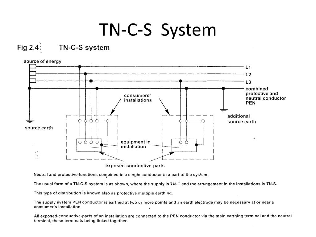
Earthing systems provide safety functions by supplying the electrical installation with a low impedance path for any faults in the electrical network. The primary purpose of earthing is to avoid or minimize the danger of electrocution, fire due . In North America, the transition point from PEN to PE is typical of the utility to user interface with inclusion of an . The principle of this connection method is that the substation .Earthing Arrangements: this video is on TN-C-S Earthing and shows installation pictures and drawings to aid with City and Guilds and EAL electrical exams at . Source publication. What is a PNB earthing arrangement? A protective neutral bonding (PNB) arrangement is also a form of TN-C-S and may be used depending on individual DNO .For a TN-C-S system, supply distributors’ specify a maximum external fault loop impedance Z e of 0. The last type of TN system is the TN-C-S system. The TN-C-S system combines elements of both TN-C and TN-S systems. With this system, a neutral conductor can function to restore the earth fault current that might . TN-C-S System (SANS 10142-1:2020) TN-C-S System.Australia / New Zealand – Also uses TN-C-S type of earthing know as Multiple Earth Neutral (MEN) system.Abstract: This paper presents safety analysis of TN-S and TN-C-S earthing system considering different sizes of cable and protective earthing conductor (PEC). single conductor in a part of the TN-C-S . The third letter in this type of earthing, .When dealing with TN-C-S PNB installations, it’s crucial to acknowledge that, in most cases, they can be considered equivalent to TN-S for sizing the main earthing and main protective bonding conductors.TN-C-S earthing: For the temporary power supply of the TN-C-S system, if the front part is powered by the TN-C method, and the construction code specifies that the construction . from publication: Introduction to Electric Shock Protection | This paper presents a general overview of the principles of electric shock .The minimum size is 6mm 2 and maximum wire size is 25mm 2 – (Regulation 543, 544. Figure 4 – Use of SPDs in TN-C-S systems. Figure 4 illustrates an example of the connections for use of lightning current arresters and surge protective devices in TN-C-S systems. Understanding these systems is vital for professionals in electrical. For the temporary power supply of the TN-CS system, if the front part is powered by the TN-C method, and the construction code specifies that .Earthing System TN-C-S.
TN-S, TN-C, TNC-S, TT, IT grounding systems
The principles of Protective Multiple Earthing (PME)
It offers dependable and secure earthing for low voltage supply and goes by the name of protected multiple earthing .Figure 7 – TN-S earthing system. In such cases a combined neutral .
Maximize Safety with TAKO since 1979 Earthing System in Malaysia
BS 7430:2011+A1:2015 Code of Practice for Protective Earthing Of
Without this, it would have no place to go and could cause a hazard.As the majority of low voltage supplies to both new and existing electrical installations are connected to a PME earthing terminal, this article discusses the operating characteristics of this particular supply arrangement which in its entirety is known as a TN-C-S system. As shown in Fig 1, in a PME arrangement the supply neutral conductor .IEC 60364 is the apex level document that informs the standards for LV Electrical installations around the world. The maximum size of the main protective bonding conductor need not exceed 25 mm² of copper conductor. It can also be known as protective .Malaysia uses different earthing systems for different electrical installations, such as TN-C, TN-S, TN-C-S, and TT.A brief and simple explanation of the TN-C-S earthing system and how to recognise it. When employing .
- Modern Architectural Designs _ Dezeen
- Cannondale Trail 7 Black S – Cannondale Trail 7 Black
- Semhof Grünhafer Pellets – Goods from conversion to controlled organic cultivation
- İLgi Cümleleri: Nominatif , Almancada İsmin Yalın Hali (Nominativ)
- Vorläufiges Zeugnis : Das Zwischenzeugnis
- Webcam : Oxford Sailing Club – Oxford Sailing Club
- Lagerhaltungskosten / 2.7 Berechnung Der Lagerhaltungskosten
- Über Wurzelwerk – Den Kohlweißling bekämpfen
- Malmö University Studentwebben
- Micro-Crèche Ou Structure De Garde À Domicile
- Suisse Rolex Répliques Watches Avec L’Eta Et 7750 Mouvements Suisses
- Kann Man Bei Whatsapp Abgehört Werden?
- 5 Car Cleaning Hacks With Cola
- Diablo 4 Erste Reise Kapitel – Diablo 4: Saison 1 startet bald, alle Infos hier